Simple Wireless Power Transmission Circuit to Glow an LED
Simple Wireless Power Transmission Circuit to Glow an LED
In this project, we will build a basic low powered wireless transmitter circuit to glow an LED.
Components Required
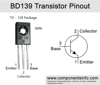
- Transistor BD 139
- LED
- Hook up wires
- 1.2k resistors
- Copper wires
- 1.5V battery
Circuit Diagram
The schematics, for transferring electricity wirelessly to glow an LED, is simple and can be seen in the below image, It has two parts, Transmitter, and the receiver.
Construction of the Wireless Power Transmission Circuit
Here the transistor used is NPN Transistor, any basic NPN transistor can be used here like BD139.
Coil is the crucial part in wireless energy transfer and should be built carefully. In this project, the coils are made using copper wire of 29AWG. Center tapped coil formation is done on the transmitter side. is used and a cylindrical coil wrapper like PVC pipe is required to wind the coil.
For the transmitter, wind the wire till 17-turns, then the loop for center tap connection and again make 17 turns of coil. And for the receiver, make a 34 turns of coil winding without the center tap.
Working of the Wireless Electricity Transfer Circuit
This circuits is powered using a 1.5V battery. The circuit can’t be used for more than 1.5 volt power supply as transistor may heat up for excessive power dissipation. However, for more rating, additional driving circuits are needed.
This wireless electricity transmission is based on the Inductive coupling technique. The circuit consists of two parts- Transmitter and Receiver.
In transmitter section, the Transistor is generating high-frequency AC current across the coil and the coil is generating a magnetic field around it. As the coil is center tapped, the two sides of the coil start to charge up. One side of the coil is connected to the resistor and another side is connected to the collector terminal of NPN transistor. During the charging condition, the base resistor starts to conduct which eventually turns on the transistor. The transistor then discharges the inductor as the emitter is connected with the ground. This charging and discharging of the inductor produces a very high frequency oscillation signal which is further transmitted as a magnetic field.
On the receiver side, that magnetic field is transferred into the other coil, and by the Faraday’s law of induction, the receiver coil start producing EMF voltage which is further used to light up the LED.
Applications of Wireless Power Transmission
Wireless power transfer (WPT) is a widely discussed topic in the electronics industry. This technology is growing rapidly in the consumer electronics market for smartphones and chargers.


Comments
Post a Comment